Robbin B. Sotir & Associates, Inc.
"Soil Bioengineering/Biotechnical
Stabilization of a Slope Failure"
Robin B. Sotir
Principal, Robbin B. Sotir & Associates Inc., Marietta, Georgia
John T. Difini
Engineer, Haley & Aldrich, Inc., Cambridge, Massachusetts
Andrew F. McKown
Vice President, Haley & Aldrich, Inc., Cambridge, Massachusetts
ABSTRACT: This paper describes the basic principles of steep slope stabilization using soil bioengineering to reconstruct and stabilize a section of slope along Massachusetts Turnpike at Mile 79.3 E.B. Discussions will focus on the principles of soil bioengineering and reinforced soil slope (RSS) designs, benefits of this interdisciplinary environmentally sound approach, and case study details: vegetation harvesting and storage, design, installation and project status as of October 1997. Design of a fill material, satisfying both agronomic needs of vegetative components and engineering requirements for slope stability, is described. Meeting environmental and aesthetic goals was paramount.
Use of tensile inclusions made from live branches and polymeric geogrids made it possible to construct a highly steepened 4V:1H vegetated earthen buttress slope.
RSS is useful in constructing steepened slopes, improving stability and reducing required fill volumes. Soil bioengineering uses woody vegetation installed perpendicular to the slope face on constructed fill terraces. The installed branches offer immediate reinforcement as supplemental tensile inclusions.
1 INTRODUCTION
Mechanically stabilized earth (MSE), or reinforced soil slope (RSS) embankment systems are commonly used for the widening and reconstruction of existing roads and highways. This paper focuses on the benefits achieved by combining the principles of soil bioengineering and reinforced soil slope design to reconstruct a failed slope on the Massachusetts Turnpike.
2 SYSTEM OVERVIEW
2.1 Soil Bioengineering and Biotechnical Slope Stabilization Techniques
Soil bioengineering techniques have been used around the world for centuries and were used in the United States by the Department of Agriculture's Soil Conservation Service in the 1930s. They have since been incorporated into the USDA's National Resources Conservation Service Engineering Field Handbook as Chapter 18, "Soil Bioengineering for Upland Slope and Erosion Control." Soil bioengineering uses mechanical, hydrological, biological, and ecological principles to develop living structures for the stabilization and revegetation of cut and fill slopes. Living woody plant material forms the main structural component. Soil bioengineering is typically used in conjunction with sound engineering data and design, a fact that is especially evident on this project.
In this case, live cuttings from woody plants were installed in the ground in specific configurations and served immediately as soil reinforcements, horizontal drains, barriers to earth movement and hydraulic pumps or wicks. Much the same as with geogrids, additional stabilization occurs when the roots develop along the length of the embedded stems. Woody vegetation, when properly designed and installed in these specific configurations, can create stable, composite earth masses. Its functional value has been well established. These cuttings can be used alone or in combination with geosynthetic materials.
When living vegetation is combined with inert components such as geogrids, the approach is referred to as biotechnical stabilization. Essentially the vegetated geogrid is a composite of soil bioengineering and an RSS system in which the slope will always be dependent upon the RSS structural measures for stability. This case study project represents an excellent example of how to combine technologies.
2.2 Engineering a Reinforced Soil Slope
The design approach to engineering an RSS is a generic process that is typical from slope to slope.
2.3 Anticipated Benefits
The combination of RSS and soil bioengineering systems typically provides the following benefits:
3 CASE STUDY
3.1 Project Site
The project site is located immediately adjacent to the eastbound lane of the Massachusetts Turnpike at Mile 79.3 in Charlton, Massachusetts. The slope was approximately 144.87 meters (475 feet) in length, ranged from 3.05 meters (10 feet) to 15.25 meters (50 feet) in height and had a slope angle of approximately 1V:1.5H. Stabilization was needed to remediate ongoing surficial sloughing failures. These failures ultimately formed a large exposed, unvegetated area that was increasingly vulnerable to progressive surface erosion and further failure. Groundwater seepage, saturated surficial soils, and seasonal freeze-thaw cycles exacerbated the instability of this north-facing slope. On both sides of the failed area, the slope was well vegetated and appeared stable; however, it was apparent that the failure was expanding on both sides, as shown in Figure 1.
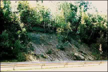 Figure 1 Overall view of project from the west-bound lane (Sept. 1994), prior to slope excavation and slope reconstruction
Subsurface conditions at the site include widely graded, slightly cohesive, dense to very dense glacial till overlain by shallow surficial topsoil and forest mat. Bedrock is typically located within 3.05 meters (10 feet) of the base elevation of the slope. However, during construction an outcrop of poor rock was discovered along a 7.62 meter-long (25 feet) section of the slope. The rock sloped unfavorably toward the roadway and required controlled blasting to cut it to a stable surface on which the slope could be reconstructed.
3.2 Project Background
Due to the nature and extent of the failure condition, the Massachusetts Turnpike Authority (MTA) decided it was imperative to correct this situation by reconstructing the slope. See Figure 1. If not treated, these conditions would inevitably lead to further slope failures, additional maintenance costs and an expanding, unsightly, unvegetated slope along a scenic stretch of the Turnpike. A concrete barrier was installed along the base of the slope to contain the failed soil mass and prevent it from moving onto the roadway.
The aim of the project was to design and construct a 4V:1H earthen buttress immediately in front of the cut slope to provide internal, external, and compound stability. The soil bioengineering approach was adopted to meet the requirement of an aesthetically pleasing and environmentally sound reconstruction, and to assist in controlling internal drainage. This combined approach uses vegetated geogrids to provide the much-needed surficial stability and to support long-term vegetative growth with almost no maintenance requirements. The geogrid is a hybrid design that incorporates brushlayers in the frontal, wrapped portion of the RSS. Over time the live branches take root and increase the internal stability of the reinforced slope.
3.3 Remedial Design
The remedial design called for excavating the failed slope back approximately 6.1 meters (20 feet) to the same slope angle (4V:1H) as the proposed slope and constructing a steepened, biotechnically stabilized earthen buttress. The slope was stabilized with layers of primary and secondary geogrids, burlap, vegetated geogrids at the face, and live fascines over the top of the finished slope. Figure 2 shows a cross section depicting the existing slope (dashed line) and the remedial design.
The brushmattress method is a system of living branches that form a cover over the streambank, providing immediate protection (Fig. 4). It is a useful system on high-velocity, steep-gradient streams where a bank can be cut back. This method roots and grows into an excellent natural riparian habitat zone.
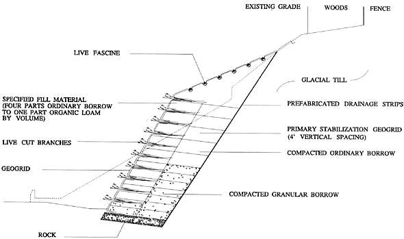 Figure 2. Cross section of remedial slope design
As shown in Figure 3, the secondary geogrid, burlap, and brushlayers (which together constitute the vegetated geogrid) were primarily designed to provide facial stability to the slope. As shown in Figure 2, the secondary geogrid and burlap "wrap" the face of each vertical lift between each row of brushlayer branches. The burlap temporarily prevents soil from sloughing out the face through the grid openings until the plant materials produce leaves and roots. The face wrap extends .91 meters (3 feet) into the slope at the bottom of each vertical lift and 1.52 meters (5 feet) at the top. All lifts were constructed using a continuous batter board to control the slope of the face. A front view of the vertical and lateral limits of the vegetated geogrid lifts and brushlayers is provided in Figure 4.
Brushlayers consisting of 2.44 to 3.05 meters (8 to 10 feet) long willow (salix sp.) and dogwood (cornus sp.) branches were placed on the constructed earthen terraces between each .91 meters (3 feet) vertical lift. These brushlayers, which are installed in layers with the growing ends exposed, extend from the face approximately 3.05 meters (10 feet) back to the mid-point of the slope. During the growing season, these brushlayers will root and produce leaves, stabilizing the face of the slope. They will also provide some measure of internal stability initially and over the long term. The alternating sequence of constructed earthen terraces and live branch brushlayers is shown in Figure 5.
Drainage panels (1.52 meters (5 feet) wide, spaced 4.57 meters (15 feet) on center) that extend vertically along the back side of the slope were designed to accommodate the migration of groundwater into the reinforced portion of the slope, preventing the buildup of hydrostatic pressures in that area. These panels connect into a .305 meter (1-foot) thick crushed-stone drainage layer at the base of the slope, which extends the full length and width of the slope.
As shown on Figure 1, four types of backfill were used to reconstruct the slope in addition to the crushed-stone drainage layer at the base. These backfills are granular borrow, ordinary borrow, 50/50 mix, and specified fill. The first three constitute the structurally competent core while the specified fill at the face provides a media amenable to plant growth. The specified fill used in the front 3.05 meters (10 feet) of each lift is a blended material consisting of four parts ordinary borrow to one part organic loam by volume. It should be noted that the lifts were constructed to slope away from the face (ù20¼) and that fertilizers were added to each lift to further optimize the growing conditions for the installed brushlayers.
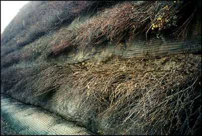 Figure 3. Close-up view of the vegetated geogrid along the front face.
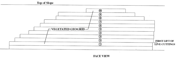 Figure 4. Front view of as-built slope illustrating limits of slope remediation activities.
A 1V:3H cut was made above the steep slope and live fascine bundles were installed to prevent surface erosion and to rapidly revegitate the slope with woody plant materials. As illustrated in Figure 6, a live fascine is a collection of live cut branches grouped together in a bundle and secured with twine. The bundle was placed in trenches and anchored with dead stout stakes and live stakes. These structures provide immediate mechanical stabilization and erosion control and will eventually grow and reinforce the surface soil mantle. In this particular application, they also act as a drain, collecting water and transporting it laterally to both ends of the site.
3.4 Stability Analyses
A series of slope stability analyses were conducted to design the RSS and assess the stability of the slope under temporary construction conditions (i.e., the cut slope condition). These analyses were conducted using the University of Texas at Austin UTEXAS3 program.
For design of the slope, stability analyses were conducted to determine: (1) the width of the reinforced zone required to provide a minimum safety factor of 1.5 for deep-seated failure surfaces, and (2) the vertical spacing and design strength of soil reinforcement elements required to provide a minimum factor of safety of 1.3 for both internal and compound failure surfaces. For temporary construction conditions, stability analyses were conducted to configure the cut so that a minimum factor of safety of 1.2 was maintained during the construction process. The computer output for the global stability analysis used to determine the lateral extent to the reinforced zone is provided in Figure 7. The failure surface yielding a minimum factor of safety of 1.5 generally defines the extent of the reinforced zone.
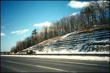 Figure 5. The alternating sequence of constructed earthen terraces and live branch layer.
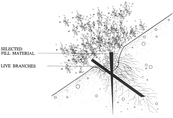 Figure 6. Establishing live fascine.
3.5 Agronomic and Geotechnical Considerations
The design and construction of this slope presented several challenges involving the need to balance agronomic and geotechnical requirements. The factors to be balanced were these: (1) the need for water and nutrients in the slope to sustain and promote vegetative growth versus the desire to remove water so as to eliminate hydrostatic pressures; (2) the need to use organic matter in the slope to provide nourishment for plant growth and development versus the desire to construct the slope with free-draining, inorganic, granular soils; and (3) the need to construct the slope during the fall and winter months while the vegetative plant materials were in a dormant state versus the desire to construct the slope during warmer weather to prevent soil freezing problems and weather delays. A final agronomic consideration was that the plant materials needed to be properly stored following harvesting to protect them from shock. A brief discussion of each of these topics follows.
Drainage - The original design called for a continuous backslope drainage system to intercept groundwater before it enters the reinforced portion of the slope and divert it to the gravel subbase and drainage system beneath the slope. The back slope drainage system was originally designed to consist of free-draining crushed stone, with filter fabric against the naturally deposited glacial soils. However, since it was desirable to allow some water to migrate to the willow and dogwood branches in the slope, the design was modified to utilize 1.52 meters (5 feet) wide prefabricated drainage strips spaced 4.57 meters (15 feet) on center in place of the continuous crushed-stone backslope layer. That allows some groundwater to migrate into the reinforced zone without permitting hydrostatic pressures to develop on the back side of this zone. The brushlayers also function as horizontal drains, reducing the possibility of hydrostatic pressures.
Organic material - To provide favorable conditions for plant growth, it was desirable from an agronomic standpoint to incorporate organic material in the backfill. To accommodate this, the outer 3.05 meters (10 feet) of slope, starting approximately 1.52 meters (5 feet) up from the base of the slope, was backfilled with a blended material consisting of four parts of ordinary borrow to one part loam by volume. By carefully selecting the mixture and the location within the slope and checking the global stability and location of failure planes, it was possible to satisfy both the agronomic and geotechnical design requirements.
Construction time frame - The freezing of subgrade soils that contain high organic material and water was a daily concern, since the construction was done mostly during the winter months. To minimize the impact of freezing, the lifts were adequately compacted at the end of each workday, and were inspected the following day for the occurrence of heave or formation of ice lenses; in addition, unsuitable frozen subgrade soils were removed when needed. Furthermore, frequent snow-storms limited the number of workdays on the project's already tight schedule. Accumulating snow, which had to be plowed from the previously constructed lifts before work could continue, shrunk staging and storage areas significantly. It should be noted that a near record snowfall in excess of 254 centimeters (100 inches) occurred during the winter this slope was constructed, following an unseasonably warm fall.
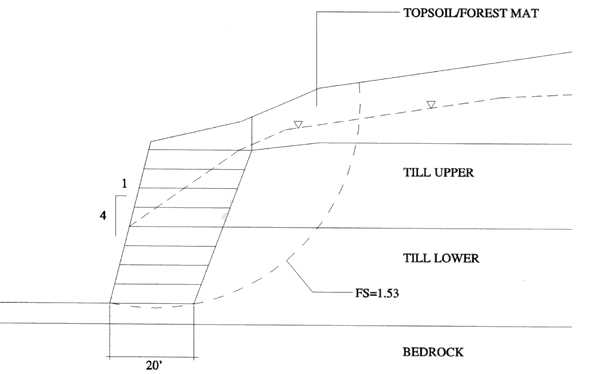 Figure 7. Factor of safety for deep-seated global failure surface.
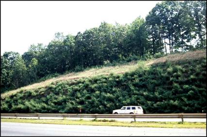 Figure 8. The condition of the project site, July 1996
Harvesting, handling and storage of cuttings - The harvesting of suitable, biotechnically capable plant material and installation of the soil bioengineering systems needed were carefully planned, coordinated and maintained. Numerous potential harvest sites were located before the project started. Sites were then selected based on the quality of material, site accessibility, and proximity to the project site. These harvesting sites contained large stands of willow (Salix sp.), a species well suited for soil bioengineering construction. Refrigerated trucks were used to transport and store the live cut branches, which allowed the cuttings to be stored for long periods of time, such as a month or more. Proper temperature and humidity controls were maintained to keep the branches in dormancy and prevent the cuttings from dying out. The use of refrigerated trailers allowed the contractor to transport larger quantities of material to the site, providing installation crews with immediate access to live cuttings when needed and improving overall operations and efficiency.
4. CONCLUSIONS
The face of the major slope reconstruction, the vegetated geogrid, looks very good. As shown in Figure 8, the slope is stable and the vegetation is well developed. The cut slope above is also well vegetated and appears stable.
This biotechnical installation should continue to root and grow, thus providing for increased surface protection, soil reinforcement, and an aesthetically pleasing revegetated slope. Over time, natural invasion from the surrounding plant community is expected to occur, causing the system to blend into the naturally wooded scenic setting of the area. Thus the long-term mechanical and ecological goals of the project will be satisfied.
REFERENCES
Gray, D.H. and Sotir, R. (1995).
Biotechnical and Soil Bioengineering Slope Stabilization. A Practical Guide for Erosion Control,
John Wiley & Sons, New York, NY, USA.
Kraebel, C.J. (1936).
Erosion Control on Mountain Roads.
USDA Circular No. 380, 43 pp.
Coppin, N., Barker, D., and Richards,I. (1990)
Use of Vegetation in Civil Engineering.
Butterworth's: Sevenoaks, Kent, England.
Gray, D.H. and Leiser, A.T. (1982).
Biotechnical Slope Protection and Erosion Control,
Van Nostrand Reinhold, New York, N.Y. USA.
3221 Stoney Acres Drive
Kennesaw, Georgia 30152
Phone: 770-424-0719
sotir@sotir.com
©2020 Robbin B. Sotir & Asociates, Inc.